
Imagine this scenario: You are standing right in the middle of your new house building site. The morning sun is shining, the smell of fresh-cut wood fills the air, and the framing crew is waiting for your go-ahead. You unroll the massive set of blueprints, searching for the structural plans. You stare at a confusing 2nd-floor joist diagram, hoping it will make sense. Instead, it looks like a chaotic maze of intersecting lines, strange arrows, and cryptic numbers.
If this situation makes you sweat, you are definitely not alone! Understanding these building blueprints is crucial, but they can feel incredibly intimidating at first glance. However, that specific diagram holds the ultimate key to the structural safety of your entire house.
Why is it so important to understand this specific drawing? Because making a mistake here does not just lead to a squeaky floor. Misinterpreting these plans can lead to costly material errors, structural sagging, and major building code violations. You want a second floor that feels solid when you walk on it, not one that bounces like a trampoline! By learning to read these diagrams, you ensure code compliance, prevent costly teardowns, and save significant time on your project.
| Step | Action | Key Checks |
|---|---|---|
| 1 | Identify overall span | Measure from wall to wall or beam; note max joist length (e.g., 2×10 spans 15 ft). |
| 2 | Check spacing & direction | Look for o.c. marks (16″/24″); arrows show run perpendicular to walls. |
| 3 | Locate openings | Find stair/hatch headers with doubled joists and trimmers. |
| 4 | Verify sizing & supports | Read labels for size (e.g., 2×12), hangers, blocking; cross-reference span tables. |
| 5 | Note subfloor & extras | Confirm plywood thickness; check for bridging or fireblocking. |
Floor Joist Fundamentals
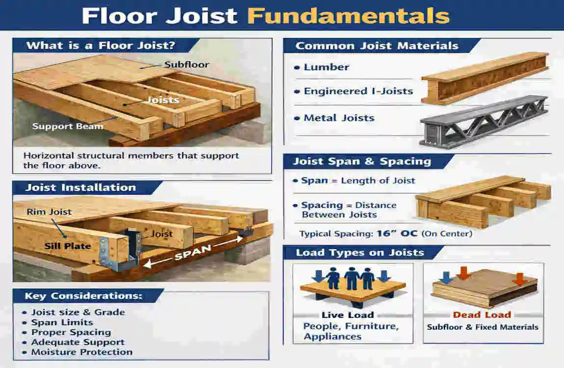
Before we start decoding the complex symbols on your building plans, we need to understand what we are actually looking at. What exactly is a floor joist?
Think of floor joists as the structural skeleton of your home. They are the heavy, horizontal wooden beams that span across the open spaces of your rooms. These wooden members rest on top of your walls and larger support beams, forming the solid base for the second floor above the first. When you walk upstairs in your home, the floorboards you step on are directly attached to these hidden horizontal supports.
Materials Used in House Building
In standard residential house building, you will typically see a few specific types of materials used for this job:
- Dimensional Lumber: This is your traditional, solid wood framing. Builders commonly use 2×8, 2×10, or 2×12 pieces of spruce, pine, or fir. The heavier the load, the wider the piece of wood needs to be.
- Engineered Wood (TJI Joists): Modern builders love using engineered wood products. These look like giant wooden “I-beams” (similar to steel beams in skyscrapers). They feature a solid top and bottom piece connected by a middle web of oriented strand board (OSB). They are incredibly strong, perfectly straight, and can span much longer distances than traditional solid wood.
Why the 2nd Floor is Different
You might wonder why a 2nd-floor joist diagram differs from a first-floor plan. The second floor comes with unique challenges!
First, modern homes often feature wide-open living rooms and kitchens on the ground floor. Because you have fewer walls downstairs to support the ceiling, the joists above must span much longer distances. To handle these massive open spaces, the second-floor framing must interact carefully with heavy-duty girders and load-bearing support beams. For example, your diagram might show a massive girder (labeled G-1) spanning a 34,000-millimeter gap to hold up the center of the upstairs bedrooms. The joists transfer the weight of the second floor to that girder, which then safely carries it down to the foundation.
Key Components of a 2nd Floor Floor Joists Diagram
When you look at your building plans, you’re seeing a top-down, bird’s-eye view of the home’s skeleton. The architect uses a specific visual language to tell the framing carpenters exactly what to do. Let’s break down the main elements you will spot on the page.
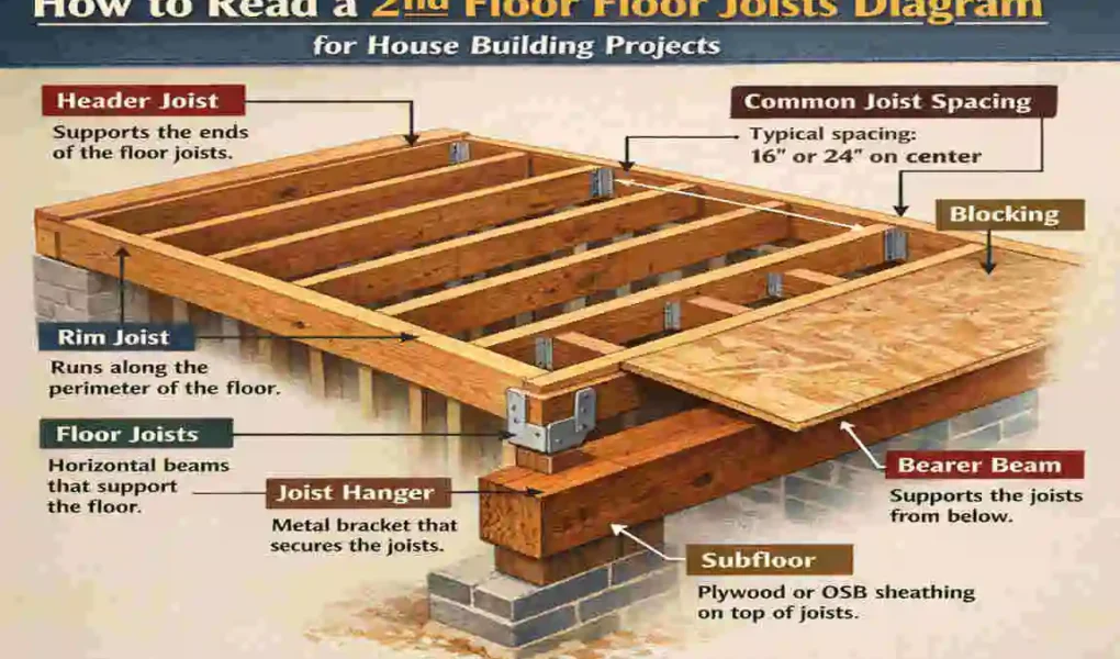
The Main Framing Members
First, look for the main structural pieces. You will often see labels like J-1 to J-8. These represent the individual floor joists repeating across the room. Next, look for thicker, bolder lines labeled B-1 to B-7 or G-1. These represent the heavy beams and girders that carry the main loads.
You will also see rim joists running along the very outside perimeter of the floor. These cap the ends of the regular joists, tying them together and providing the exterior wall with a solid base. Around staircase openings, you will spot headers and trimmers, which are doubled-up pieces of wood that frame the open hole safely.
Decoding the Symbols
The lines on the paper tell you where the wood goes, but the symbols tell you how it gets placed. You will see long, double-sided arrows stretching across a room. These arrows point out the exact direction the joists need to run.
Right next to these arrows, you will find size notations. For instance, you might see a note that reads: 38×184 mm spruce at 300mm centers. This tells the builder the exact species of wood, the specific dimensions of the board, and how far apart to space them.
Recognizing Supports and Connections
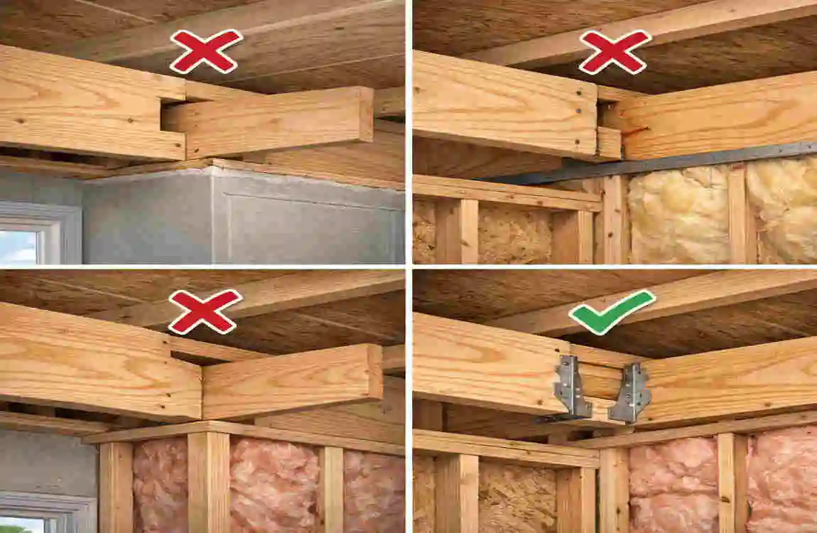
Gravity is always pulling downward. Therefore, every single horizontal board needs a vertical support. Your diagram will show where the joists rest on wall plates, heavy girders, or vertical posts. For extra-long stretches (up to 16-6 feet), the diagram might specify using metal hangers to fasten the wood to the main beams securely.
To make things easy, here is a quick reference table of the components you will encounter:
Component Description: Typical Notation on Diagram
Floor Joists: The main horizontal spans supporting the floor (e.g., 2×12 wood joists spaced 16 inches apart). Labeled as J-1 to J-8, usually accompanied by a long directional arrow.
Beams and Girders: Heavy structural members that transfer loads to the foundation. Drawn with thick, bold lines, often featuring dimensions like 2700-7200 mm.
Rim Joists: The perimeter enclosure that wraps around the outside edge of the house framing. Shown on the precut outer edges, where the OSB subfloor ties in.
Blocking: Small, short cross-pieces of wood are installed between the long joists to stop twisting. Shown as staggered, dashed lines between the main parallel lines.
Step-by-Step: How to Read a 2nd Floor Floor Joists Diagram
Now that you know the vocabulary, it is time to put your skills to the test. Let’s walk through the exact process a professional builder uses when they unroll a fresh set of plans. Follow these five simple steps, and you will understand your framing layout in no time.
Check the Scale and Orientation
Before you look at a single piece of wood, you must orient yourself to the page. Look in the bottom corner of the blueprint for the scale block. The scale tells you how the drawing translates to real life. For example, you might see a note saying “1/4 inch = 1 foot.” This means that every quarter-inch you measure on the paper equals one actual foot of distance on your job site.
Next, find the North arrow. This helps you align the paper with your actual building lot. Once you know which way is North, look at the exterior wall dimensions. You will usually see measurements formatted like 14′-6″ (which means 14 feet and 6 inches). Measure the walls first to understand the overall size of the box you are framing.
Identify Joist Direction and Spacing
Now, scan the interior of the rooms on the drawing. Look for those long, double-sided arrows we mentioned earlier. These arrows show you the layout direction. Joists almost always run perpendicular (at a 90-degree angle) to the main support beams underneath them.
Right next to the arrow, you will see a crucial abbreviation: OC. This stands for “On Center.” When the plan says 16″ OC or 19.2″ OC, it means the builder must measure from the dead center of one wooden joist to the dead center of the next. Spacing is critical! If you space them too far apart, the floor will not have the load capacity to hold up heavy furniture or multiple people.
Decode Sizes and Spans
You know which way the boards run and how far apart they sit. Next, you need to know the size of the boards. The architect calculates this based on two factors: the span (the distance the board spans without support) and the load (the weight the floor supports).
You must match the spans to the engineering tables in the diagram’s notes section. For example, the notes might specify a 2×8 piece of lumber for short spans of 8 to 9 feet spaced at 24″ OC. However, for a wide-open living room, it might call for a massive 2×12 board.
You also need to note the load requirements listed on the page. Architects design standard residential bedroom floors to handle a “live load” of 40 psf (pounds per square foot). Live loads include people, pets, and movable furniture. Understanding these numbers helps you see why the architect chose specific wood sizes.
Spot the Supports and Connections
A floor is only as strong as what holds it up. Take your finger and trace a line along one of the joists on the paper. Where does it end? It should terminate on a wall or a large beam.
Trace the large beams to see where they transfer their weight. They usually end on top of thick wooden posts or steel columns that go straight down to the basement. Pay very close attention to connection details. The diagram will tell you if the joist rests on top of the beam, or if you need to use specific galvanized metal hangers to attach it flush to the side. Look for notes about notches, too, as removing too much wood can weaken the board.
Verify the Subfloor and Finishes
Finally, look for the instructions regarding the “skin” that covers the skeleton. The diagram notes will detail the subfloor requirements.
Usually, the plans will ask for OSB (Oriented Strand Board) or thick plywood ties. You might see a note requiring ¾” thick tongue-and-groove OSB, glued and screwed to the joists. This step is vital because a properly installed subfloor stops the joists from twisting and makes the entire floor system rigid and squeak-free.
Real Examples from 2nd Floor Floor Joists Diagrams
Theory is great, but let’s look at how this plays out in the real world. Analyzing real sample layouts helps train your eyes to spot important details.
Imagine you are looking at a sample framing plan for a large, modern home. Right down the middle of the house, you see a thick, bold line labeled G-1. This is the main central girder.
Branching off from this central girder, you see a series of parallel lines labeled J-1 through J-8. The diagram shows these joists spanning distances of 2700 to 7200 millimeters. Because the span of 7200 mm (over 23 feet) is incredibly long, the architect specifies engineered wood I-joists rather than traditional solid wood. Traditional wood would sag under that distance!
Let’s look at another very common layout trick builders use to save money. Suppose a room has a total span of 16 feet. Using a massive 2×12 solid-wood joist to span that 16-foot span would be very expensive.
Instead, the architect might draw a mid-girder along the 8-foot centerline of the room. Because the joists only have to cross an 8-foot gap now, the diagram can specify smaller, cheaper 2×8 joists. You still get a perfectly strong, safe floor, but you save hundreds of dollars on lumber costs! Reading the diagram closely helps you understand the clever engineering behind the house design.
Common Mistakes and Troubleshooting
Even experienced builders can misread a complex blueprint when they are in a rush. Unfortunately, fixing framing errors is a nightmare once the drywall goes up. When you review your plans, keep a sharp eye out for these classic mistakes:
- Ignoring the OC Spacing: This is the most frequent DIY error. If the diagram calls for 16″ on-Center spacing and you accidentally install them 24″ apart to save wood, your floor will lack the necessary support. It will bounce when you walk, and the ceiling below will likely crack over time.
- Misreading Maximum Spans: Every size of wood has a breaking point. A standard 2×12 board can safely span up to 16 feet 6 inches, depending on the wood species. If you misread the scale and try to stretch a 2×12 over an 18-foot span, you create a dangerous overload situation.
- Overlooking Building Codes: Diagrams must align with local rules. Many builders forget to double-check their plans against the International Residential Code (IRC) or local municipal standards for second-floor loads.
How to Fix These Issues: Always keep a structural span table in your pocket or on your phone. If a span on the drawing appears too long for the specified wood size, pause the project. Consult the span tables to verify the math. If you still have doubts, never guess! Hire a structural engineer to review the drawing. A quick consultation fee is vastly cheaper than rebuilding a collapsed living room.
Advanced Tips for House Building Projects
If you want to take your building skills to the absolute next level, you need to look beyond the paper.
Modern residential construction relies heavily on Building Information Modeling (BIM) software. Instead of trying to visualize flat lines, builders can use BIM programs on their tablets to transform the 2D diagram into an interactive 3D model. You can virtually walk through the framing, zoom in on tricky beam connections, and spot potential plumbing conflicts before you ever pick up a saw.
Furthermore, always remember that diagrams must be customized for your specific geographical location. For example, if you are planning residential builds in active seismic zones like Lahore, standard framing rules change. You will need a 2nd-floor joist diagram that incorporates specialized earthquake tie-downs, heavy-duty shear walls, and reinforced metal strapping to keep the second floor attached to the first during heavy vibrations.
Frequently Asked Questions (FAQs)
We covered a massive amount of information! Let’s review by answering the most common questions beginners ask when tackling these blueprints.
What does OC mean in a 2nd-floor joists diagram?
OC stands for “On Center.” It is the measurement from the exact center of one wooden board to the exact center of the board next to it. For example, 16″ OC means there is a 16-inch gap between the middles of the framing members, ensuring the floor weight is distributed evenly across the room.
How far can standard 2nd-floor joists span?
The maximum span depends entirely on the size of the wood, the species of the lumber, and the spacing. However, as a rule of thumb, a heavy-duty 2×12 wooden joist spaced at 16 inches on center can safely span up to 16 feet and 6 inches. For longer spans, you must upgrade to engineered wood or steel.
What is the difference between a 1st-floor and a 2nd-floor diagram?
While they look visually similar, they handle different types of weight. A first-floor diagram focuses heavily on supporting the main living areas and transferring weight straight into the concrete foundation. A second-floor diagram must detail how to safely carry the loads above the ceiling (such as bedrooms, heavy bathtubs, and roof supports) across the wide-open spaces of the rooms below.